


Project Overview
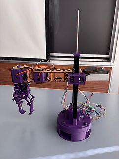
CAN-BOT is a 4-DOF SCARA pick-and-place robot designed to autonomously grab and sort recyclable cans and bottles from a trash pile into recycling containers. The system combines analytical kinematics, joint-space PD control, and a force-sensing gripper to execute a fully autonomous pick, transport, and release sequence.
Skills and Tools:
Conceptual Robot Architecture Design
Denavit-Hartenberg (DH) Parameter Derivation
Forward Kinematics (Analytical, 4-Link Transformation Matrix)
Inverse Kinematics (Analytical + Numerical via MATLAB ikcon)
5th-Order Polynomial Trajectory Planning (jtraj)
Jacobian Analysis and Singularity Detection
MATLAB Robotics Toolbox Simulation
Onshape 3D CAD Design
3D Printing and Laser Cutting (FDM, PLA)
Arduino Motor Control
Team Leadership and System Integration


Features and Specifications:
Architecture: RPRRR SCARA
Joint Limits: Revolute joints +/-140 deg, end effector +/-180 deg
Workspace: Approximately 1.2 m x 1.2 m x 0.35 m reachable envelope
Trajectory Planning: 5th-order polynomial joint interpolation (zero initial/final velocity and acceleration)
IK Accuracy: Position and orientation error below 10^-6 m and rad
Controller: Joint-space PD with kinematic acceleration model
Sensing: Embedded force sensor in gripper for contact confirmation and grasp force threshold
Fabrication: 80/20 aluminum extrusion column, 3D-printed and laser-cut links, four-bar linkage gripper
Contents
Feb 2026
May 2026
Boston University
Robotics

Problem and Task
Recycling facilities rely heavily on manual labor to sort materials from mixed waste streams, a task that is repetitive, time-consuming, and error-prone. The challenge was to design and build a robot that uses at least 2 revolute joints and 1 prismatic joint to achieve a goal.
My Tasks:
Designed and fabricated the end effector in Onshape.
Derived the forward kinematics analytically using DH parameters across all four links.
Contributed to trajectory planning using 5th-order polynomial interpolation
Led system integration and assembly, coordinating across subteams to verify that all mechanical, electrical, and software components were built and connected correctly before testing.
Constraints
The arm had to reach across a representative trash pile workspace without exceeding the structural limits of 3D-printed and laser-cut links.
The gripper had to grasp cans and bottles of different diameters.
Engineering Solutions
Mechanical
End Effector
Designed a four-bar linkage gripper in Onshape driven by a single servo motor, converting rotary servo output into symmetric inward claw motion.
Force sensor embedded on the inside surface to detect when the gripper has made contact with an object.
Sensor placement was determined during the CAD phase, accounting for gripper closing geometry, sensor thickness, and wire routing to avoid interference with the four-bar linkage motion.
Arm Structure
80/20 aluminum extrusion used as the vertical column for rigidity and ease of assembly.
3D-printed joint housings connect the servo motors to the laser-cut links and maintain consistent joint axis alignment throughout the range of motion.
Prismatic joint repositioned to the base to minimize cantilevered load and reduce deflection at the end effector.

Electrical

MKS (Motor Driver) Board:
Three servo motors drive revolute joints 2, 3, and 4, receiving PWM commands
One stepper motor drives the prismatic joint, providing linear vertical displacement through a lead screw.
Software
Forward Kinematics (MATLAB)
Manually derived DH parameters for all four links, constructing individual transformation matrices A1 through A4 using standard DH conventions.
Compounded matrices to produce T04, the full end-effector pose expressed as a 4x4 homogeneous transformation, capturing position and orientation relative to the base frame.
Verified FK output numerically using MATLAB's SerialLink fkine function against the analytical result.
Inverse Kinematics (MATLAB)
Derived closed-form IK analytically: q2 from the law of cosines, q1 from atan2 with a correction term, q3 from the prismatic height equation, and q4 from the orientation constraint.
Implemented a multi-guess numerical IK function using ikcon with five initial joint configurations, selecting the solution minimizing a weighted combination of position and orientation error.
Verified IK accuracy with position errors below 10^-6 m and orientation errors below 10^-6 rad.
Trajectory Planning (MATLAB)
Task-space waypoints (home, above bottle, grasp, above bin, release) converted to joint-space targets via the analytical IK function.
5th-order polynomial trajectories generated between each waypoint pair using jtraj, enforcing zero velocity and acceleration at all waypoint boundaries for smooth, jerk-minimized motion.
Joint position, velocity, and acceleration profiles plotted across all four joints to verify trajectory continuity.
PD Controller (MATLAB)
Joint-space PD controller drives each joint from its current position toward the next waypoint target.
Desired velocity set to zero at each waypoint, causing the robot to fully settle before advancing to the next segment.
Controller loop exits when both joint position error and joint speed fall below defined convergence thresholds.

Testing
Verified FK output by comparing the analytical T04 matrix against MATLAB SerialLink fkine across multiple joint configurations.
Validated IK accuracy for a test pose, confirming position and orientation errors of effectively zero across all six DOF.
Identified kinematic singularities by sweeping q2 across its joint range and evaluating the determinant of the planar Jacobian submatrix, confirming singularity at q2 = 0 deg (fully extended configuration) with manipulability w dropping to zero.
Validated on physical hardware that all three servo motors and the stepper-driven prismatic joint responded correctly to Arduino commands.
Confirmed consistent, readable force sensor output.

Results
In simulation, the robot successfully completed the full autonomous pick-and-place sequence, with the PD controller smoothly converging to each waypoint and IK errors below 10^-6 m and rad across all tested poses. The workspace scatter plot confirmed a reachable envelope spanning roughly 1.2 m x 1.2 m x 0.35 m with no gaps near the target operating region.
On physical hardware, servo and stepper actuation functioned correctly under Arduino control and the force sensor produced consistent output, but fully coordinated autonomous operation was not demonstrated within the project timeline.
IK Position Error: < 10^-6 m
IK Orientation Error: < 10^-6 rad
Singularity: Confirmed at q2 = 0 deg (full arm extension)
Manipulability at Singularity: w = 0
Simulation: Full pick-and-place sequence completed successfully
Hardware: Individual subsystems validated; full autonomous sequence not deployed
Lessons Learned
Moving the prismatic joint to the base was the most impactful mechanical decision. It reduced the moment on the entire system, but it required another full DH derivation mid-project.
Singularities must be identified and excluded from the workspace during trajectory planning rather than handled later. The q2 = 0 singularity falls within the joint limits and had to be explicitly avoided.
Hardware motor integration should be scoped and started much earlier. The simulation worked, but moving to physical Arduino commands took longer than expected and compressed the deployment timeline.
Laser-cut link dimensions determined the physical link lengths the kinematic model used. Any dimensional error in fabrication would have introduced IK error over the workspace.


