


Project Overview
The P1 Albatross (MPA) is a conceptual turbofan-powered maritime patrol aircraft designed as a cost-effective replacement for the Lockheed P-3 Orion. Developed in Boston University's ME408 Aircraft Performance and Design course, the aircraft was sized and optimized to match the anti-submarine warfare and surveillance capability of contemporary competitors at roughly half the price, achieving a projected unit cost of $135M against a competitor average of $245M.
Skills and Tools:
Aircraft Mission Analysis and Segment Performance Estimation
Design Point Selection (Thrust-to-Weight / Wing Loading Constraint Diagram)
Weight Estimation and Empty Weight Fraction Analysis
Airfoil Selection and Wing Geometry Design
Fuselage Volume and Geometry Sizing
Empennage Design and Stabilizer Sizing
Propulsion System Selection and Engine Sizing
Takeoff and Landing Performance Analysis
Structural Load Analysis (Wing and Fuselage Shear and Moment Diagrams)
Spar, Longeron, and Skin Sizing
Material Selection for Aerospace Structures
Static Stability, Control Surface, and Rudder Design
Aircraft Cost Modeling and Competitive Market Analysis


Features and Specifications:
Propulsion: 4x CFM56-3B2 Turbofan (SFC: 0.9316, 22,000 lb thrust each)
Gross Takeoff Weight: 140,148 lb (lighter than P-3, P-8, and P-1)
Wing: NACA 654-421, b = 81.1 ft, AR = 10.0, taper = 0.234, sweep = 20.5 deg
Fuselage: L = 97.7 ft, max diameter = 11.3 ft, fineness ratio = 0.116
Mission Radius / Endurance: 1,300 nm / 4 hrs on station
Mission Efficiency: 37.18% (competitor avg: 33.62%)
Cruise / Loiter: Mach 0.71 at 43,000 ft / Mach 0.50 at 30,000 ft
Takeoff / Landing Field Length: 7,497 ft / 3,682 ft
Design Load Factor: 5.25 (limit: 3.5, safety factor: 1.5)
Projected Unit Price: $135M vs. $245M competitor average (2025 dollars)
Contents
Sep 2025
Dec 2025
Boston University
Aircraft Design

Problem and Task
The Lockheed P-3 Orion has been out of production since 2000 and its available replacements, the Boeing P-8 Poseidon and Kawasaki P-1, carry price tags roughly five times higher. The challenge was to design a new maritime patrol aircraft that maintained competitive anti-submarine warfare capability and on-station endurance while targeting a dramatically lower unit cost through careful configuration, propulsion selection, and mission profile optimization.
My Tasks:
Led structural design, computing wing and fuselage shear and bending moment diagrams for the critical loiter-speed load case, then sizing spars, longerons, and skin panels to meet stress ratio requirements
Selected Stainless Steel 301 Full Hard as the primary structural material based on cost, weight efficiency, and corrosion performance in maritime environments
Contributed to airfoil selection, evaluating three NACA 6-series candidates and selecting the NACA 654-421 for its superior Clmax, lowest Cdmin, and drag bucket coverage across all operating points
Contributed to mission analysis and design point selection, working through the T/W vs. W/S constraint diagram to balance takeoff field length, climb gradient, landing distance, and stall speed requirements
Constraints
Takeoff field length could not exceed 7,500 ft and landing had to stay above 2,500 ft, constraining the T/W and wing loading design space and driving flap sizing decisions.
The design load factor of 5.25 was set by the loiter condition at 1,000 ft, where dynamic pressure is 2.8x higher than at cruise altitude, making low-altitude patrol the structural sizing case for the entire airframe.
All technology factors were held at 1.0, meaning cost and weight targets had to be achieved through configuration and sizing choices alone rather than advanced materials or novel propulsion.
The aircraft had to be priced below the P-8 and P-1 while generating profit over a 150-aircraft production run, requiring the weight and cost model to stay tightly coupled throughout the design process.
Engineering Solutions
Mechanical
Physical Model
3d printed a miniture model of the theoretical aircraft.
Model was designed in Solidworks and printed using PLA.

Electrical

No Electrical Solutions
Software
This project was done with equations and calculations from the book Design of Aircraft by Thomas C. Corke and Boston University Professor James Geiger's extensive Aircraft Design Excel Spreadsheet.
Mission Analysis:
The patrol mission consists of two cruise legs at Mach 0.71 and 43,000 ft (185 min each), two loiter segments at Mach 0.50 at 30,000 ft (120 min each), and a pre-landing loiter.
Loitering at 30,000 ft due to upgraded sonobuoy technology, reducing drag-induced fuel burn and yielding a mission efficiency of 37.18%.
Airfoil and Wing Design:
Three NACA 6-series airfoils were evaluated against Clmax, Cdmin, drag bucket width, and leading-edge radius.
The NACA 654-421 was selected for its highest Clmax of 1.285, lowest Cdmin of 0.0045, and drag bucket spanning Cl = 0 to 0.8, covering all operation points.
The wing was designed with AR = 10.0, taper ratio = 0.234, and 20.5 deg leading-edge sweep, achieving a span of 81.1 ft and reference area of 657.6 ft².
Fuselage Design:
The fuselage was scaled from the P-3 Orion's interior volume to match its passenger compartment (4,260 ft³) and cargo hold (1,315 ft³) while reducing length to 97.7 ft and diameter to 11.3 ft.
A tricycle landing gear was selected with a 21 ft wheel track and 35 ft wheelbase optimized for ground stability.
Empennage Design:
Both stabilizers use a NACA 0012 symmetric airfoil for zero lift at zero incidence, low base drag (Cd0 = 0.0060), and structural suitability at high subsonic speeds.
Chosen over NACA 0009 for higher Clmax (1.5 vs. 1.2) and a better T/C ratio.
A conventional tail was selected over a T-tail to minimize weight.
30% of the rudder span outside the horizontal stabilizer wake for spin control compliance.
H-stab and V-stab were sized to volume coefficients of 0.545 and 0.08 respectively.
Propulsion System:
Four turbofans were selected over turboprop alternatives for their lowest bare engine weight (4,301 lb each), sufficient thrust (22,000 lb per engine), and an SFC of 0.9316 within the optimal range.
An engine scale factor of 0.9315 was applied with 2% bleed extraction, yielding an installed engine weight of 8,013 lb and engine volume of 168 ft³ per unit.
Takeoff and Landing:
Slotted trailing-edge flaps with cf/c = 0.25 and bf/b = 0.46 were selected after field length, landing distance, and unit cost evaluation.
The final design achieved a takeoff field length of 7,497 ft, a landing distance of 3,682 ft, a stall speed of 125.5 ktas, an AEO climb rate of 2,358 ft/min, and an OEI climb gradient of 387 ft/min.
Structural Design:
Load Analysis:
Loiter at 1,000 ft condition governs all structural sizing, producing a limit load factor of 3.5 and a design load factor of 5.25.
Wing shear and moment peak at the root, driven by flap lift with negative contributions from fuel, engines, and missiles.
Fuselage bending is negative (concave downward) at the wing attachment due to weight of fuel, payload, and wing lift.
Spar, Longeron, and Skin Sizing:
Wing spars: 18 x 26 in at 0.90 in thickness, compressive stress ratio 0.993
Fuselage longerons: 2 x 2 in, 5 per quadrant, 0.1674 in thickness, stress ratio 0.995
Wing skin: 67 mils (tensile stress ratio 0.971); fuselage skin: 35 mils (stress ratio 0.967)
Material Selection:
Stainless Steel 301 Full Hard was chosen over aluminum for its ability to be rolled thinner to equivalent strength.
Magnesium was rejected due to corrosion risk in maritime operating environments.
Stability, Control, and Rudder Design:
The rudder was sized for the OEI asymmetric power case with a deflection angle of 16 deg, chord ratio Cr/Cvs of 0.2, and an asymmetric power coefficient of 0.0208, achieving a 0.1% tolerance margin.
Cost and Market Analysis:
Projected unit price of $135M (2025 dollars), a P/P_avg ratio of 0.552.
Production modeled as 150 aircraft at 1 month each, with 2 RDT&E prototypes at 16 months each, all at technology factor 1.0.
Gross empty weight of 140,148 lb is competitive, directly reducing manufacturing and operating costs.

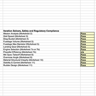
Testing
Verified design point selection by confirming the constraint diagram intersection at W/S = 95 lb/ft² and T/W = 0.299 satisfied all active takeoff, climb, landing, and stall boundaries simultaneously.
Verified weigh error due to changes was 0 lbs.
Validated mission efficiency of 37.18% by computing time-on-station as a fraction of total mission time across all five flight segments.
Checked aircraft would always point downward, preventing stall.

Results
The final design met or exceeded objectives on endurance (4 hrs), mission efficiency (37.18%), takeoff field length (7,497 ft, within threshold by 3 ft), and unit price, while achieving a radius of 1,300 nm and a gross weight of 140,148 lb, lighter than all three primary competitors. All structural components were sized to stress ratios between 0.967 and 0.995. The $135M unit price represents a 45% reduction against the $245M competitor average.
Mission Efficiency: 37.18% (competitor avg: 33.62%) ✓
Endurance: 4 hrs ✓
Radius: 1,300 nm ✓
Gross Weight: 140,148 lb (lighter than P-3, P-8, P-1) ✓
Takeoff Field Length: 7,497 ft (threshold: 7,500 ft) ✓
Unit Price: $135M vs. $245M competitor average ✓
All stress ratios: 0.967 to 0.995 ✓
Lessons Learned
The loiter altitude is the most consequential mission parameter for structural sizing. The 2.8x dynamic pressure increase from cruise to low-altitude loiter drives the load factor, spar depth, and skin thickness.
Material selection for maritime aircraft cannot only be chosen based on density. SS301's ability to be rolled thinner than aluminum makes the density penalty smaller than it first appears. Magnesium's poor corrosion resistance disqualifies it entirely.
Using technology factors at 1.0 forced the design to compete on configuration and mission profile efficiency.
The design point constraint diagram proved to be the most critical synthesis tool of the early design phase, affecting all field performance, climb, and stall requirements.


