


Project Overview
Balance Kart is a motor-controlled kart designed to transport a vertical 8020 aluminum extrusion beam across a specified distance and back without toppling it over. The cart uses closed-loop control to dynamically maintain speed and acceleration throughout its motion.
Skills and Tools:
SolidWorks 3D CAD Models
SolidWorks Motion Study Simulations and Calculations
3D Printing
Arduino IDE
Laser Cutting
Closed-Loop Control
Friction Fitting


Features and Specifications:
Motion: Up to 12 ft (Forwards and Backwards)
Power: Tethered wall power
Overall Dimensions: 125 x 200 x 60 mm (4.9 x 7.9 x 2.4 in)
Top Speed: Up to 630 mm/s
Top Acceleration: Up to 320 mm/s^2
Input: Arduino Uno IDE (C++)
Controller: Arduino Uno
Closed Loop Control: Dynamically maintains top speed and acceleration while in motion
Contents
Nov 2024
Dec 2024
Boston University
Electromechanical Design

Problem and Task
The goal of this project was to design and build a motorized cart capable of balancing a vertical beam while driving from one point to another and returning to its starting position. The cart needed to demonstrate controlled acceleration and deceleration profiles calculated to keep the beam upright throughout the entire motion.
My Tasks:
Calculate force profiles in Solidoworks Motion Study.
Design and fabricate motor holder and wheels.
Constraints
The cart was required to fit within a shoe box volume (roughly 300 × 150 × 100 mm), limiting the overall footprint and height of the design.
An Arduino Uno and motor driver were required as the control system, with closed-loop feedback to dynamically maintain the desired speed and acceleration.
The maximum acceleration was constrained by the beam's tipping threshold, requiring SolidWorks motion simulations and hand calculations to determine safe operating limits.
Component selection was limited to available workshop parts and 3D printed PLA components.
Engineering Solutions
Mechanical
Cart Base:
The base is a laser-cut wooden slab shaped into a rectangle.
The area had to be large enough to accommodate a motor, Arduino Uno, motor driver, and extrusion.
Drivetrain:
Wheels feature a three-spoke design for a sporty aesthetic and reduced material use during printing.
A V-shaped groove on the tread seats a rubber O-ring for increased traction.
Wheels are friction fit onto the axel, which rides on sanded 3D printed mounts to reduce friction.
A GT2 timing pulley on the axel transfers power from the motor via belt drive.
The motor is secured by a custom 3D printed mount with a timing pulley on its output shaft.

Electrical

Arduino Uno:
The board served as the central controller, connected to the 12V gear motor through the L298N motor drive controller. The motor driver regulated voltage and current to the motor, while the Arduino interfaced directly with the driver to execute speed and acceleration commands.
Software
Arduino IDE (C++):
The user inputs max velocity, acceleration, and distance into the code. The cart accelerates from standstill to top speed, maintains that speed, decelerates, and stops at the target distance before reversing the full sequence to return to its origin. A closed-loop routine continuously monitors motor velocity and adjusts output to match the desired profile throughout motion.
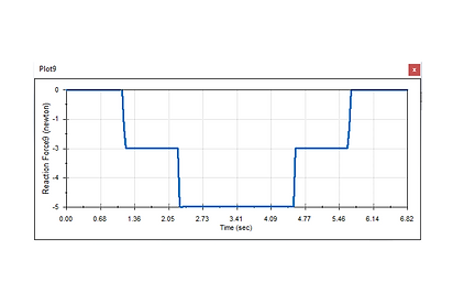
SolidWorks Motion Study:
Maximum acceleration was first determined through hand calculations, then validated using SolidWorks motion simulations. Force vs. time plots were generated at peak acceleration. If the force reached 0 N or doubled the baseline (5 N), the beam would be at the tipping threshold. Real values values would be slower than the calculated ones due to external experimental factors such as the floor debris, cart level, and motor performance.

Testing
The kart drove to varying distances multiple times 8 and 12 ft. Horizontal drift, speed, time for completion, and direction of tipping was observed and noted. Force curves were adjusted to prevent tipping. Friction fitment between the wheels and shaft was tightened, preventing wheel camber during motion. This ensured a straight drive path.
Results
The kart sucessfully traveled a total of 12 ft, forwards and backwards, on a flat surface without toppling the 8020 extrusion. On an official observed run, the cart completed its mission 5 ft forwards and 5 ft backwards (10ft) from standstill in 8 seconds.

Motion: Up to 12 ft (Forwards and Backwards)
Power: Tethered wall power
Overall Dimensions: 125 x 200 x 60 mm (4.9 x 7.9 x 2.4 in)
Top Speed: Up to 630 mm/s
Top Acceleration: Up to 320 mm/s^2
Input: Arduino Uno IDE (C++)
Controller: Arduino Uno
Closed Loop Control: Dynamically maintains top speed and acceleration while in motion
Lessons Learned
Initial lateral drift caused by wheel friction fit was identified early in testing and resolved through adjustment.
Mounting the Arduino and motor driver with tape was functional but resulted in a poor weight distribution when the components shifted during tests.
The SolidWorks motion model assumed ideal conditions. Real-world factors caused deviations from the calculated power requirements.
Future iterations should account for real-world friction coefficients during the simulation phase to produce more accurate and deployable results from the start.


