
MONET MACHINE
Monet Machine

Project Overview
When: 9/30/2024 - 11/4/2024
Where: Boston University
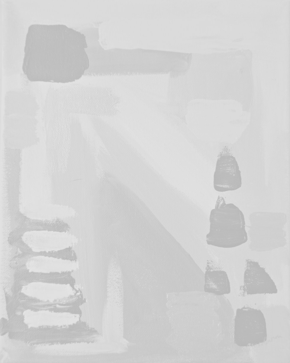
Monet Machine is a cartesian motion system with 2.5 degrees of freedom (DOF) that can take any image from the internet, outline the image, and paint inside the outline.
Features
Overall Dimensions:
319 x 319 x 153 mm (12.6 x 12.6 x 6 in)
Painting Area:
100 x 140 mm (4 x 5.5 in)
Speed:
Up to 5000 mm/s in any direction.
Multi-Color Capabilities:
3 Paint Colors of choice + 1 Marker
Compatible Photos:
Any photo works!
Input:
MATLAB modified CAM G-Code (JSCut)
Controller:
MKS Board
Accuracy:
+/-- 0.002 mm
Components
Existing Parts:
-
8020 Aluminum Extrusion (5)
-
Nema 17 Stepper Motor (4)
-
Limit Switch (2)
-
GT2 Belt (3)
-
GT2 Timing Pulley (4)
-
GT2 Idler Pulley (3)
-
Steel Pin (3)
-
Heat-Set Threaded Brass Insert (2)
-
MKS Board (1)
-
Clipboard (1)
-
Various Screws and T-Nuts (31)
-
Paint (3)
-
Marker (1)
-
Paint Brush (1)
3D Printed (PLA):
-
Motor Mount L Bracket (2)
-
Idler L Bracket (2)
-
Brush/Marker Holder (2)
-
Extrusion Carriage (1)
-
Carriage Motor Mount (1)
-
Holder Support + Carriage (1)
-
Limit Switch Support (2)
-
Paint reservoir (1)
External Creation
Structure:
The main structure consisted of 5 8020 Aluminum Extrusions that were hand-sawn to 254 mm (10in) with tapped holes on either side. The extrusions were held together by 3D printed L brackets and screws.
Linear Stage:
4 Nema 17 Stepper Motors were used to create the 2.5 DOF motion. 2 motors moved the x-axis, 1 for the y-axis, and 1 for the z-axis. The motors were connected to the design with a top-mounted 3D printed extrusion that either extended from an L bracket or a carriage. The motors spun a GT2 Timing Pulley which pulled GT2 Belt and carriage around an idler pulley and pin setup. The carriages were CAD designed to slide in the extrusion rails and customized to fit onto the motor mounts, extrusion, limit switch support, and holder support. The limit switches allowed for the linear stages to home on the x and y-axis.
One issue that was corrected was the poor quality of the carriage belt insert. The belt would have problems fitting into the original carriage designs, but after modifications to the CAD, the belt would fit snug.
End Effector:
3D printed paint brush and marker holders were designed to fit many common brush and marker sizes. The writing tool was secured using a set screw. The holders utilized a rack and pinion system for z-axis motion where the rack was extruded from the holders. It slid along angled T-rails on the support that allowed for painting at the same coordinates. The support for the holders was created to screw into a stepper motor, slide along the extrusion rails via GT2 belt, and act as the pinion.
Some challenges that were fixed included high friction between the T-rails, skipping gears between the rack and pinion, and fragile carriage extrusion. The T-rails were filed down to reduce friction, a perpendicular force was added to the holders via adjustable screws, and the fragile carriage was strengthened by changing the orientation of the 3D print.
Paint Reservoir/Surface:
The paint reservoir 3D printed to hold 3 paint colors and fit in the extrusion rails at a 90° angle. This would allow for the reservoir to sit flush with the painting surface.
The painting surface was created by modifying a clipboard to fit on top of 2 structural 8020 extrusions, allow for the reservoir to slot in, and be able to screw into the structure. The clipboard can hold the paper still, providing a stable surface to paint on.
Applicable Skills:
-
Conceptual Design Sketches
-
Design with Constraints
-
Caliper Measurements
-
SolidWorks 3D CAD Models
-
3D Printing
-
Part Assembly
Programming
Inkscape:
This program allows this project to take any photo and create a painting of it. A photo is uploaded to Inkscape, bitmap traced into a grayscale image consisting of 4 different gray sections, and resized to fit within a 100 x 140 mm painting area. The file is then exported as an .svg file.
JSCut:
The .svg file is imported into JSCut to create tool paths for the marker outline and each of the 3 different paints. The program spits out a .gcode file that can program the stepper motors.
MATLAB:
The .gcode file is imported into a MATLAB script that will write new lines to the .gcode that will assign each tool path to the specific writing tool and color. The code will also add the necessary movements that will program the paint brush to occasionally redip into the paint to ensure adequate paint transfer. The script automatically creates a new updated G-Code.
Reptier-Host:
The final updated G-Code file can be loaded into Repetier-Host to start the print.
Applicable Skills:
-
G-Code Tool Path Generation
-
Arduino Coding (Open Loop Control)
-
MATLAB File Reading/Writing


